Friday, 10 June 2011

Worm Gear


Description:
Worm Gear

Worm Gear Box

When worm-gear speed reducers are assembled, proper alignment of the worm and gear, and the resulting tooth contact pattern, is the most critical assembly variable. It is also the most difficult to control. Emerson Power Transmission engineers have developed and patented a new computerized mechanism to quickly and accurately align the worm and gear.
A typical worm-gear reducer assembly includes the input worm shaft straddle-mounted between ball bearings, and the output wormgear and shaft supported by tapered roller bearings. To produce these assemblies with acceptable worm-to-gear contact patterns, assemblers must position the worm-gear under the worm centerline accurately, and at the same time set output bearing endplay within a close tolerance, usually in the range of 0.002 to 0.003 in. This typically requires a trialand-error process that is neither cost effective nor precise. First, technicians apply bluing to the worm-gear, then assemble the reducer with shims either behind the bearing cups or under the retainers. Next, shim-pack thickness and location are adjusted until the correct combinationof contact pattern and bearing clearance is met. This can be time consuming, because the reducer may need to be assembled and disassembled repeatedly, and final quality depends on the skill of the assembler.
Gearing manufacturers have sought to shortcut this process by locating the theoretical worm-gear centerline relative to one bearing shoulder, and then using statistical average dimensions for bearing cup/cone stack height and housing bearing seat locations. With this technique, the same shim-pack is always used behind the rear-bearing cup, so the assembler need only adjust the outboard shim pack for correct endplay. This approach eliminates the need for bluing, but still requires disassembly of the outboard bearing retainer, and the resulting tooth contact pattern is only average at best.
It is commonly believed that a poor contactpattern will self-correct as the bronze gear wears-in over time, but the reality is that part of the worm-gear assembly's useful life is lost in the process. In addition, high contact stresses that result from a small initial contact area can cause premature scoring of the worm thread, which further accelerates gear wear while shortening life. The resulting high concentration of bronze serves to exacerbate the problem.
EPT's Emerson Gearing Div. resolved these various assembly problems by developing a computerized centering device that accurately measures each assembly component and automatically calculates exact front and rear shim-pack requirements.
First, the computer measures stack height of the output assembly. Next, the computer's master worm contacts the bronze gear and oscillates horizontally to find the exact centerline. The computer measures the reducer housing and output bearing retainer to determine the location of front and rear bearing seats relative to the housing face. A computer data screen shows the number and thickness of shims to place behind the front and rear bearing cups. This centers the wormgear and gives the desired bearing endplay.
The computerized process eliminates the need for bluing, dial indicators, multiple assemblies and disassemblies, and highly skilled assemblers. The result is a substantial saving in time, a perfectly centered tooth contact pattern, and accurate endplay settings.

Pipe cutter machine

Add caption
Product Description:

We are manufacturer & exporter of Automatic Label Printing machine in Korea. 
Items of production:: 
1. Rotary Letterpress Label Printing Machine. 
2. Automatic Label Printing Machine. 
3. Automatic Label Die-cutting Machine. 
4. Auto Slitter/Pipe cuter Machine. 
5. Auto cutter/Label roll bender/Auto rewinder. 
6. Auto Sticker detector/Sticker roll winder. 

Roll Die-cutting machine

Roll Die-cutting machine


Product Description

We are manufacturer & exporter of Automatic Label Printing machine in Korea.
Items of production::
1. Rotary Letterpress Label Printing Machine.
2. Automatic Label Printing Machine.
3. Automatic Label Die-cutting Machine.
4. Auto Slitter/Pipe cuter Machine.
5. Auto cutter/Label roll bender/Auto

Thursday, 9 June 2011

Die Mould

Die Mould

Discription

17 years mold making & molding experiences
ISO9000:2001certified factory
our products 100% export to Europe and America contries

Plastic Molds & Products
Material: ABS, PC, PP, PVC, POM, PE, PET, PU, Nylon, PA+Fiberglass,
Dimension Standard: ASTM, JIS, BS, DIN, EN, ISO

Mold standard: DME HASCO
Process: Tool-making (export molds as per customer's requirements)

1) According to buyer's product drawing and mold specification such as mold material, runner type, number of cavity, gate type, slide and its movement, as well as injection machine information if possible.
2) Or according to buyer samples we manufacture.
3) Or according to buyer concept and main function we design and manufacture.
4) Supply layout drawings for buyer's approval.
5) Supply injection samples for buyer's approval.

Our process has the following features:
Weekly emailed written updates, including issues list and photos
Consistent tracking of tool build milestones
Clear and frequent communications
Clear documentation

Written approval by our customer is required at these three stages:
Mold design approval
Sample approval
Mold delivery and approval

When your mold is completed and delivered, you don't just get the mold; you also receive:

Final 2D and / or 3D files

Final drawings

Trial results, including first shots

Process parameters used during trial runs

Wednesday, 8 June 2011

New Instoment

Dial Indicate
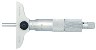
Depth Micrometer


Digital Clipper


New Dial Indicate Meter

                                                      Indicate Meter


Product Description

1)With shock-proof structure inside, perfect protecting inside structure from any shock damage
2)Inside structure is mainly made of stainless steel and copper, that helps indicators to resist any corrosion.
3)Jeweled  bearinqs  inside promise perfect sensitivity of indicator.
4)With adjustable tolerance marker and dial Iocking screw. 

Digital Indicate Meter


With shock-proof structure inside, perfect protecting inside structure from any shock damage 
Inside structure is mainly made of stainless steel and copper, that helps indicators to resist any corrosion. 
Jeweled  bearing's  inside promise perfect sensitivity of indicator. 
With adjustable tolerance marker and dial Locking screw. 

Tuesday, 7 June 2011

New Magerment

micrometer size
Vernier size

Micro & Gage


O-Rings

O-rings are primarily used for sealing. Another application is the use as drive belts. As a seal, an O-ring is a means of preventing an unwanted escape of fluid or pressure. Types of seal applications include:
______________________________________________
______________________________________________
Static seal
The mating gland parts are not subject to relative movement
______________________________________________
______________________________________________
Dynamic seal
1. Reciprocating relative motion along the shaft axis
2. Oscillating: movement around the shaft axis relative to the other member
3. Rotary: movement around the shaft axis in one direction only
4. Seat: mechanical distortion of the O-ring around a shaft in order to create the seal
______________________________________________
______________________________________________
Pneumatic seal
Similar to any of the ones previously described except it is used with a gas or a vapor rather than a liquid
______________________________________________
______________________________________________
Vacuum seal
Seals a vacuum chamber or area

Flat Washers

A flat disc with a centrally located hole
Provides a bearing surface thus minimizing surface wear
Distributes fastener loads evenly to minimize surface deformation (when tightening fasteners)
Conducts electricity
May cover large clearance holes
Has more compression strength and can handle higher forces than non-metallic

Aluminum 5712
Light weight — 1/3 the weight of steel
Good sealing capability
Non-magnetic
Good electrical conductor (30% copper)
Good heat conductor (70 btu/hr/sq ft/°F/ft)
May be anodized to increase corrosion resistance and is available in a wide variety of colors

Beryllium Copper 5718
Good electrical conductor (17-22% copper)
May be heat treated for higher strength
Corrosion resistant
Non-magnetic
Good heat conductor (68 btu/hr/sq ft/°F/ft)
Good vase metal for plating
Excellent spring material

Brass 5714
Good electrical conductor (26% copper)
Non-magnetic
Excellent plating base
Corrosion resistant — especially in a marine environment
Good heat conductor (70 btu/hr/sq ft/°F/ft)

Copper 5716
Excellent electrical conductor (100% copper)
Excellent sealing capability
Corrosion resistant
Good plating base
Excellent thermal conductivity (225 btu/hr/sq ft/°F/ft)
Non-magnetic

Steel 5702
Least expensive metallic washer
Good plating base
Fair electrical conductor (12% copper)
Most commonly used material
Highest strength for cost

Flat Washers


Flat Washers & Nuts Bolt

Bracket&Clamps

Used to retain, clamp, support or locate one component to another in an assembly

Angle 4928, 4929, 4925, 5950
Used to support or brace two surfaces perpendicularly to one another


Flat 4930, 4931
Used to support or brace two surfaces on the same plane
Component/Hold Down 2811, 2810
Used to clamp one component or surface to another

Cord/Strain Relief 5356, 5355, 5357, 5358
Used to clamp around a cord to eliminate tension on the cord connections normally inside an electrical box

Retaining* 5310, 5311
Used to clamp tube, wire, hose or pipe in its proper location in an assembly
Cable* 5300, 5301
Used to hold clamp wire or tube in its proper location in an assembly

* Retaining and Cable clamps are very similar in application though    styles vary

 Bracket

 Bracket&Clamps

 Bracket&Clamps

 Bracket&Clamps
The cord clamps prevent wires from being pulled off of terminals.

Sparing washer

Objective


Applies a predetermined force on adjacent members in an assembly.
Dampens vibration.
Eliminates side or end-play.
Controls end pressure.
Keeps fasteners secure.
Accommodates thermal or pressure expansions and contractions.
Applies drag or resistance to turning.
Available in Beryllium Copper and Spring Steel (carries higher loads).

Sparing washer


Crescents 5804
Supports relatively light loads with relatively wide deflection range
Uniform spring rate over deflection range
Best suited for applications which require flexibility, frequent load cycling and light loads
Linear load-deflection characteristics
Single Wave 5807
Similar to crescent washers with a flat bearing surface to minimize abrasion for soft assemblies/surfaces

Saturday, 4 June 2011

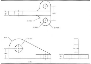
Autocad draft

Draf  Desined by Atif Raees