Sheet Metal Forming
Bending is a metal forming process in which a force is applied to a piece of sheet metal,
causing it to bend at an angle and form the desired shape. A bending operation causes deformation along one
axis, but a sequence of several different operations can be performed to create a complex part. Bent parts
can be quite small, such as a bracket, or up to 20 feet in length, such as a large enclosure or chassis. A
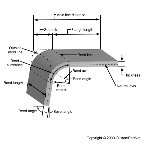
bend can be characterized by several different parameters, shown in the image below.
 Bending Diagram
- Bend line - The straight line on the surface of the sheet, on either side of the bend, that
defines the end of the level flange and the start of the bend.
- Outside mold line - The straight line where the outside surfaces of the two flanges would
meet, were they to continue. This line defines the edge of a mold that would bound the bent sheet
metal.
- Flange length - The length of either of the two flanges, extending from the edge of the sheet
to the bend line.
- Mold line distance - The distance from either end of the sheet to the outside mold line.
- Setback - The distance from
either bend line to the outside mold line. Also equal to the difference between the mold line distance
and the flange length.
- Bend axis - The straight line that defines the center around which the sheet metal is bent.
- Bend length - The length of
the bend, measured along the bend axis.
- Bend radius - The distance
from the bend axis to the inside surface of the material, between the bend lines. Sometimes specified
as the inside bend radius. The outside bend radius is equal to the inside bend radius plus the sheet
thickness.
- Bend angle - The angle of the bend,
measured between the bent flange and its original position, or as the included angle between perpendicular
lines drawn from the bend lines.
- Bevel angle - The complimentary angle to the bend angle.
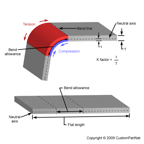
The act of bending results in both tension and compression in the sheet metal. The outside
portion of the sheet will undergo tension and stretch to a greater length, while the inside portion experiences
compression and shortens. The neutral axis is the boundary line inside the sheet metal, along which no tension or
compression forces are present. As a result, the length of this axis remains constant. The changes in length to the
outside and inside surfaces can be related to the original flat length by two parameters, the bend allowance and
bend deduction, which are defined below.
 Neutral Axis
- Neutral axis - The location in the
sheet that is neither stretched nor compressed, and therefore remains at a constant length.
- K-factor - The location of the neutral
axis in the material, calculated as the ratio of the distance of the neutral axis (measured from the inside
bend surface) to the material thickness. The K-factor is dependent upon several factors (material, bending
operation, bend angle, etc.) and is typically greater than 0.25, but cannot exceed 0.50.
- Bend allowance - The length of
the neutral axis between the bend lines, or in other words, the arc length of the bend. The bend allowance
added to the flange lengths is equal to the total flat length.
- Bend deduction - Also called the
bend compensation, the amount a piece of material has been stretched by bending. The value equals the
difference between the mold line lengths and the total flat length.
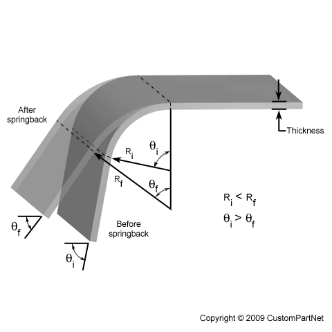
When bending a piece of sheet metal, the residual stresses in the material will cause the sheet to
springback slightly after the bending operation. Due
to this elastic recovery, it is necessary to over-bend the sheet a precise amount to achieve the desired bend radius
and bend angle. The final bend radius will be greater than initially formed and the final bend angle will be smaller.
The ratio of the final bend angle to the initial bend angle is defined as the springback factor, KS.
The amount of springback depends upon several factors, including the
material, bending operation, and the initial bend angle and bend
radius.
 Springback
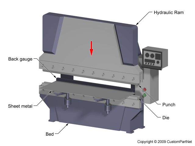
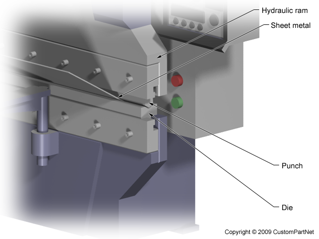
Bending is typically performed on a machine
called a press brake, which can be manually or automatically
operated. For this reason, the bending process is sometimes
referred to as press brake forming. Press brakes are available
in a range of sizes (commonly 20-200 tons) in order to best suit
the given application. A press brake contains an upper tool
called the punch and a
lower tool called the die, between which
the sheet metal is located. The sheet is carefully positioned over
the die and held in place by the back gauge while the punch
lowers and forces the sheet to bend. In an automatic machine, the
punch is forced into the sheet under the power of a hydraulic
ram. The bend angle achieved is determined by the depth to which
the punch forces the sheet into the die. This depth is precisely
controlled to achieve the desired bend. Standard tooling is often
used for the punch and die, allowing a low initial cost and
suitability for low volume production. Custom tooling can be used
for specialized bending operations but will add to the cost.
The tooling material is chosen based upon the production quantity,
sheet metal material, and degree of bending. Naturally, a
stronger tool is required to endure larger quantities, harder
sheet metal, and severe bending operations. In order of increasing
strength, some common tooling materials include hardwood, low
carbon steel, tool steel, and carbide steel.
 Press Brake (Open)
 Press Brake (Closed)
While using a press brake and standard die sets, there are still a variety of techniques that can be used to
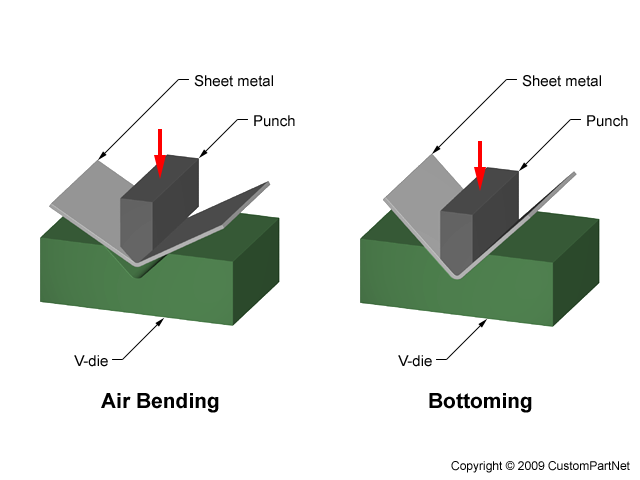
bend the sheet. The most common method is known as V-bending,
in
which the punch and die are "V" shaped. The punch pushes the sheet
into the "V" shaped groove in the V-die, causing it to bend.
If the punch does not force the sheet to the bottom of the die
cavity, leaving space or air underneath, it is called "air bending".
As a result, the V-groove must have a sharper angle than the angle
being formed in the sheet. If the punch forces the sheet to the
bottom of the die cavity, it is called "bottoming". This technique
allows for more control over the angle because there is less
springback. However, a
higher tonnage press is required. In both
techniques, the width of the "V" shaped groove, or die opening, is
typically 6 to 18 times the sheet thickness. This value is referred
to as the die ratio and is equal to the die opening divided by the
sheet thickness.
 V Bending
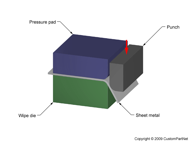
In addition to V-bending, another common bending method is wipe bending,
sometimes called edge bending. Wipe bending requires the sheet to
be held against the wipe die by a pressure pad. The punch
then presses against the edge of the sheet that extends beyond the
die and pad. The sheet will bend against the radius of the edge of the
wipe
die.
 Wipe Bending
Design rules
- Bend location - A bend should be located where
enough material is present, and preferably with
straight edges, for the sheet to be secured without
slipping. The width of this flange should be equal
to at least 4 times the sheet thickness plus the
bend radius.
-
Bend radius
- Use a single bend radius for all bends to eliminate additional tooling or setups
- Inside bend radius should equal at least the sheet thickness
- Bend direction - Bending hard metals parallel to the rolling direction of the sheet may
lead to fracture. Bending perpendicular to the rolling direction is recommended.
- Any features, such as holes or slots, located too close to a bend may be distorted. The
distance of such features from the bend should be equal to at least 3 times the sheet thickness
plus the bending radius.
- In the case of manual bending, if the design allows, a slot can be cut along the bend line
to reduce the manual force required.